How Can We Help?
AIR FLOW WITHIN CLAMPS
WHY:
Air flow is the major thermodynamic process resulting in heat exchange with clamps. Yet, owing in large to the difficulties of the work environment, I don’t think it’s been properly measured. It is difficult to put sensors in precise locations in clamps and keep them there (and find them again). It is wet and cold, which is not good for electronics, and there are many chances for a sensor to sustain hard knocks. Accurate measures of air flow would allow more accurate models of clamp temperature. It would also give greater insight into what happens in a clamp over a storage campaign – does the air flow in the clamp relative to the outside change as a result of reduced permeability/ the clamp settling/ beets shrinking as they dry?
HOW:
In the open air, air speed is usually measured with a vane anemometer – something that looks like either a fan, or three cups spinning around a vertical axis. The next common alternative is a hot wire anemometer. These are a little more fragile, but also a little more accurate at low air speeds. They are also a lot smaller. And, most importantly, they have successfully been used to directly measure air speed in a post-harvest setting – in large crates of apples. This is the approach I want to copy for sugar beets. The devices would obviously be larger, and probably hard wired to allow them to run longer than the 28 hours these are described to survive.
There are even more alternatives. An ultrasonic anemometer looks a good option (eg here and here), in that they are generally built for tough environments and have good resolution and low airspeed range e.g. 0.12 m/s. They seem popular in the nautical world. The downside to them is that they are expensive. We’re talking 5000-7000 SEK per sensor, before you add in the data logging and power equipment. There are cheaper, more ‘home user’ type systems (eg here), but it’s not clear that they’ll hold up under this working environment. They also don’t have the accuracy of the more expensive units.
Beyond this, temperature is probably the best proxy we have to direct measure of air speed, mainly because the sensors can definitely tolerate the environment. By measuring how quickly a change in temperature moves through a clamp, we can derive how quickly the air is moving. The downside is that we need to measure at higher rate than that you’d measure if you were just interested in temperature or if air speed was measured directly, so there will be huge amounts of data. There would also be a lot of noise in the measurement.
Another alternative is pressure. Pressure is a direct correlate with air speed – that is, if we could measure air pressure differentials in a clamp, we would be able to accurately derive air speeds. Something like this has been done for large piles of mine tailings, but I’ve not been able to work out how this would work with sugar beets. The direction of the wind matters when measuring pressure and I don’t know how this could be done in a unidirectional manner. But at least the sensors are less expensive and tougher.
Which ever metric is used, there is a need good and reliable coverage through the profile of the clamp. My hope would be one sensor every 100cm at least, starting about 50cm from the ground. So three rows, 12 sensors per cross section? I would also want the sensors to be in for the whole campaign, if we’re to look at the question of “do air flow dynamics change over the year?”. For it to be fully valuable in terms of modelling the system, need to link the measurements of air speeds on the inside to air speeds on the outside, and to all other factors that may impact air flow, such as cover type and clamp architecture.
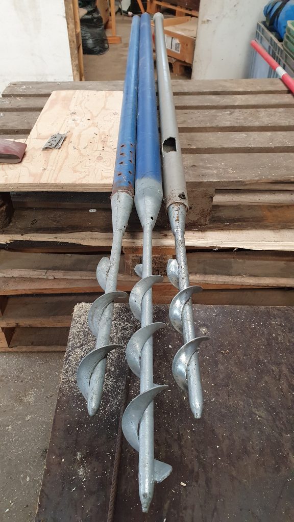
And just as a final note, we’ve been trying to do some exploratory measurements. In 2018, we managed to see clear differences in air flow through a pipe that was sitting in a clamp just above ventilation pipes, depending on whether the ventilation system was on or off. This was a big pipe with many holes and we could use a vane/fan type anemometer. Now we want to try deep in the clamp at specific points and at low velocities. The idea now is that we’d drive a perforated pipe into the clamp, push a thermal anemometer into the perforated zone, and then measure. This only measures in 2D, but still, it’s a good beginning. The issue we have had include: The first pipe being too small, the Bluetooth connection to the thermal anemometer dropping out about 20cm into the (2nd) steal pipe, and the Bluetooth dropping out about 100cm into the plastic pipe (3rd attempt). Buying a new anemometer is only a 300:- proposition but is yet to be tested. Using a Bluetooth extender might be possible (400:-). While we could get further into the clamp with the plastic pipe, we couldn’t actually measure any flow, maybe because the holes in the pipe were too small, the holes were blocked, or maybe because we were in the wrong place where there was no flow. I’m starting to feel like there is a reason no one has done this before…
WHEN:
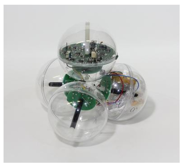
As soon as possible (campaign 2021). I’ve started to work on the electronics.
COST STAB-IN-THE-DARK:
No idea, yet. I need to work out the method first.
WHY THIS MIGHT NOT HAPPEN:
See above.
COMMENTS: