OpenFOAM – FIFTH ATTEMPT. AIR FLOW THROUGH A SUGAR BEET CLAMP w TRANSIENT SOLVER

A long time ago (2021-02-17), I wrote that I had a feeling there was something wrong with my CFD model of a sugar beet clamp – the rates of air flow seemed a bit low when compared to a few roughly similar cases. It turns out, there was something wrong with it. The viscosity of the fluid in the model – air – was dialed way up. Air at 5 degrees C has a kinematic viscosity (nu) of around 1.4 e-5 m2/s. The previous modelling attempts had it set at 5 e-2 m2/s. That’s more like diesel. Oops.
The silver lining of resolving this issue is that now I know we shouldn’t give up the hope of measuring air flow within a clamp. Also, when looking at some models of a clamp with a cover, the old figures are pretty close. More on that later – more error checking is needed first.
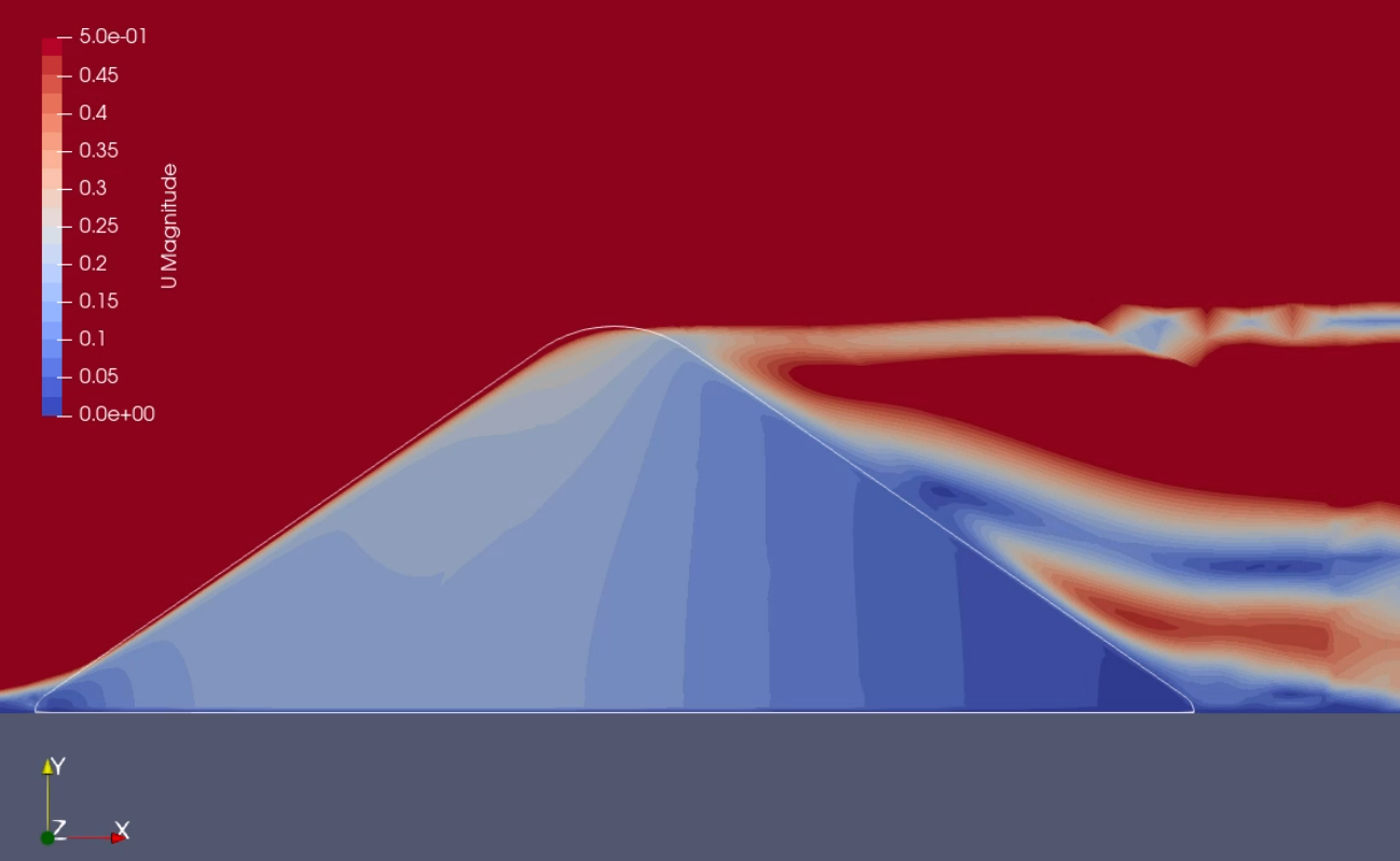
For now, the next bit of progress in sugar beet clamp CFD modelling: a transient (time varying) simulation of air through a clamp that is 9 m wide, 3 m high, no cover. Velocities in the clamp range from around 0.01 to 0.25 m/s. In the down-wind half, velocity is mainly below 0.15 m/s.
Technical details: Darcy coefficient of 101699 and Forchheimer coefficient of 367 (those that, using Tabil et al (2003)’s results, I calculated for a clamp of mixed beet size and 0% foreign material), 5 m/s air speed entering from left, nu = 1.38 e-5 m2/s, solver = pimpleFoam (incompressible, turbulent, transient), a time step of 0.001 sec, run for a 120 sec simulation (so 120 000 iterations), and all other setting taken from the pitzDaily tutoral in the pimpleFoam>RAS directory of OpenFoam v9. Run on my pretty modern laptop within OpenFOAM v9 run through WSL2, the simulation had a clock time of 3644 seconds, or ca. 61 minutes. The mesh is fairly coarse, with ca 15,000 cells.
The 120 seconds of simulation was saved with one frame per second and is condensed into a 7 second video. At the start of the simulation, the air is standing still, so the first 2 or 3 seconds of the video is the model settling itself.
It is clear that something needs to be done about the transition in the grid, where it goes from fine to coarse about 2 m downwind from the clamp – weird breaks in the contours can be seen.
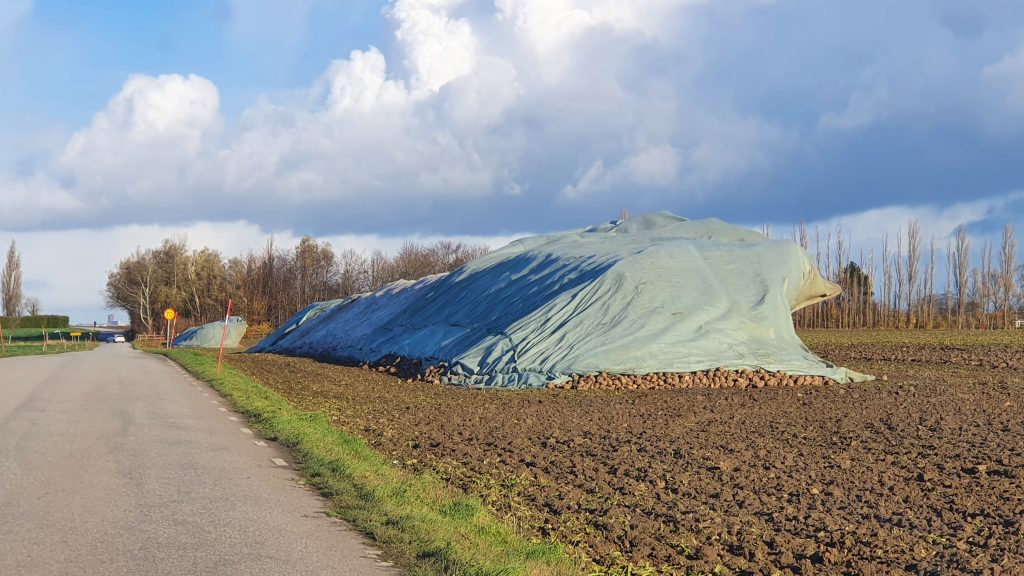
Another thing that happened a long time ago (Nov 2020) was I managed to snap this photo of covers on two clamps that had come loose. If I remember correctly, the wind was blowing harder than 5m/s, but the effect of the clamps shape on the downwind pressures is pretty clear on both the near and far clamp:

Another big step in the progress of this project is that work on it is near full-time again. This has resulted partly from a move to the Department of Energy Sciences at Lund Uni (LTH), partly from the need to get this done. It is the LTH mob that I first learnt CFD from, and it’s them that will stop more stupid mistakes entering the model. They are pros.
Next steps: Heat equation.